Piggy back or fuel management system for campro BOT
Rotational Rationale by circle track
http://www.circletrack.com
Crankshaft technology has evolved in both form and materials for the various professional racing series, even to the extent of creating significant power increases.
From the racer's point of view, a crankshaft's stroke would seem like the only dimension of any real importance. It may be, but we should not relegate the crank's other dimensional attributes to the realm of inconsequential. A crankshaft's No. 1 job is to convert the linear forces applied by combustion on the piston to rotational motion. All the power the engine is ever going to make is created above the piston crown. As a major part of the rotating assembly, a crank's job is to transmit power, as efficiently as possible, from the cylinder to the flywheel. The key words here are: as efficiently as possible. What we will examine in this article is how a crankshaft's configuration can affect its ability to efficiently convert linear power and motion to usable rotational power.
Efficiency First, let's look at crank efficiency. All too often, it is claimed that a long-stroke configuration will make more torque for a given displacement. The reason this is often quoted is that the engine has a longer lever arm with a long stroke. Although this may be true, it has sacrificed piston area, and that cancels out the stroke advantage. A longer stroke has more cylinder bore friction and limits the rod length. A long stroke signifies a shorter rod and greater friction-inducing side thrust on the cylinder wall. These factors cut output everywhere in the rpm range. These two factors alone tell us that, within limits, a short-stroke, big-bore, long-rod engine is the way to go.
, the force pushing the piston into the cylinder wall (B) is greater when rod angularity (C) goes up (as it does with shorter rods).")
Short-stroke cranks with a longer rod are mechanically more efficient than short rods and a long stroke. For a given gas pressure (A), the force pushing the piston into the cylinder wall (B) is greater when rod angularity (C) goes up (as it does with shorter rods).
Windage For the budget-orientated classes, the rule book often states that the crank cannot have knife-edged or rounded leading edges for reduced windage. I'm sure many racers have wondered just what advantage an aero crank has over a square-faced, counterweight design with a stock pattern. Some years ago, the opportunity arose to run such a test in a 383 engine. Here, Scat 331/44-inch stroke cranks of each design (aero and regular) were used because the longer stroke would more clearly show what the difference was. Also, the oil used was 20-50 Mobil. That's probably a grade thicker than what might normally be used in a typical near-stock race engine. The results (Figure 1), though almost certainly showing bigger differences than would be seen in an engine with a shorter stroke, strongly indicate the advantage of an aero crank over a regular crank.
A point to note here is that if the crankcase has a vacuum drawn on it, the advantage of an aero crank diminishes. The results in Figure 1 tell us that aero cranks are good for power output.
Coatings About 25 years ago, coatings with various properties began to find their way into the top echelons of racing. Slowly, but surely, these have developed into one more weapon in the professional engine builder's speed arsenal. Thermal barriers for heads and intakes are a common feature of many race engines, but we are looking at cranks here. The ticket here is oil-shedding, Teflon(r) based coatings. Do they help power output? Working with Calico Coatings, I ran tests-again in a 383-and got the results, which are shown in Figure 2. Conclusion: Coatings deliver, but not until fairly high in the rpm range.
 based coating by Calico Coatings. Our dyno results showed an increase in top-end output.")
This Scat cast steel aero crank has been detailed with emery rolls and given an oil-shedding Teflon(r) based coating by Calico Coatings. Our dyno results showed an increase in top-end output.
Journal Diameter For about the last five years, with no-holds-barred race engines, the trend has been to reduce rod and main bearing journal diameters wherever and whenever possible. The obvious point of this is reduced frictional bearing loss. Just how much, you may ask, can that amount to? More than you might think, as bearing loss goes up much faster than diameter does. This tends to come down significantly faster as journal size is decreased. A move some years back was to drop the normal small-block, 2-inch, big-end journal size to 1.88 inches. Although the feedback numbers vary somewhat, it seems that a gain of 5 hp at 9,000 rpm is about average. But there is more to it than just the reduction of the bearing loss. The smaller big-end journal weighs less and, as a consequence, needs less counterweight to balance it. At first, you might think it's a direct trade-off, but that actually is not the case in most circumstances. Since the counterweight is spread out over a considerable arc, much of the weight is not fully effective. Consequently, it takes more weight to balance the effect of the more compactly located mass of the piston, rod, and big-end journal. The upside of this is that if the weight is removed from either end of the counterweight (instead of removing it right at the heavy spot), a lot more counterweight mass can be removed than is lost at the big-end journal side. By keeping a close watch on piston, rod, and journal mass, significant reductions in overall crank weight and moment of inertia (MOI) can be made. Since any short and medium circle track is substantially about accelerating off the turn, a lower MOI translates directly into better acceleration. Rear wheel dyno acceleration tests of high versus low MOI rotating assemblies show that efforts put into reducing the MOI of the crank, rod, and piston assembly can easily amount to another 10 rear-wheel horsepower. The faster the acceleration rate, the bigger the difference.
Bearings and Clearance Although coatings have had some acceptance as oil-shedding mediums, the place they have found most favor is in bearings. At this point in time, it would be true to say that probably better than 50 percent of the Cup car engines are utilizing coated bearings. Personally, I hardly ever build an engine these days without coated bearings, as they have shown to take the continued abuse of extended dyno sessions and come out almost unscathed. Exactly how coatings improve bearing life is not clear, but evidence indicates that coatings not only allow the oil to flow around the journal/bearing clearance volume more easily to maintain an intake film, but also have a small amount of surface porosity that causes the oil to soak into the coating just enough to effectively combat minimal lubrication conditions. Whether that is the case remains to be seen, but not knowing how they work certainly doesn't detract from the fact that they do work.

Reduced main bearing journal size means less weight, as do hollow journals. Contrary to what might be expected, a hollow journal with the correct geometry can deliver a greater fatigue life than a solid one.
With the need to minimize the amount of oil flying around inside the crankcase, efforts have been made to keep bearing clearances down to a minimum. The smaller the bearing clearances are, the thinner the oil needed to get the job done. This means taking far more care when measuring everything and making sure the clearances are accurate. The problem for the guy on a limited budget who is building engines at home is that measuring tools can be expensive. To establish bearing clearance, two pieces of measuring equipment are needed: an internal and an external micrometer. An external micrometer can be acquired at a very reasonable price from any mass tool and equipment merchandiser, such as Harbor Freight. What seems unavailable at any price under about $600 is an internal micrometer, which measures main bores and big-end rod journal bores. At a lower price, but still far from a giveaway, is a dial-bore gauge. Many engine shops use this, but it is not exactly easy to use. Give one to 10 engine builders inexperienced with their use, and you are likely to get a main bearing measurement at 10 different sizes. The internal micrometer, on the other hand, is about as close to a sure-fire deal as it comes, regardless of how much experience the builder has with this tool.
 and aero counterweights (2) can be seen here. Dyno tests show aero makes more power.") The difference between regular flat-faced counterweights (1) and aero counterweights (2) can be seen here. Dyno tests show aero makes more power. |  | . That is why grinding under size and making the radius bigger can actually strengthen a stock-sized crank. With a 1.88-inch journal diameter, the radii on this Cup car crank are far more critical.") Cranks break through the journal radius (arrows). That is why grinding under size and making the radius bigger can actually strengthen a stock-sized crank. With a 1.88-inch journal diameter, the radii on this Cup car crank are far more critical. |
So, where does this leave those of us building our engines at a home workshop with less-than-professional shop tools? Well, there is Plastigage. This stuff is about as cheap as it comes, but it is looked down upon by almost every Cup engine builder I've ever mentioned it to. Why? Because it is not as accurate as the more correct (and expensive) tools for the job. However, I think there may be an element of techno-social climbing going on here. Having used all three of the methods mentioned, here is my take on it. First, Plastigage accuracy is not as bad as some pros would have you believe. Testing this for yourself is easy. All you need is two machine parallels and two 0.002-inch feeler gauges. Just place the two feeler gauges side-by-side on one of the parallels and place a strip of the Plastigage between the feelers. Next, place the other parallel on top and squeeze the pair in a press or vice. When you measure, the now-spread Plastigage will have a reading that is really close to the 0.002 inch that it should read. The not-so-good news is that when applied to a curved bearing and journal, things are not quite that close. Generally, the results are within about +/-0.0002 inch (i.e., 2 ten-thousandths of an inch). Maybe this is not perfect, but it is good enough for most of us if the bearings are about middle limit. Now we come to the best part of using Plastigage. If the bearing being measured is out of tolerance, it will be obvious. If the bearing clearance is wrong, especially if it is on the tight side, it will instantly show up, thus preventing serious engine damage.
Now we know how to measure bearing clearance, but how much of it should we have? For most V-8s, a good working figure is 0.002 inch (2 thousandths) for the rod journals and 0.0025 inch (211/42 thousandths) for the mains. Going up half a thousandth on this is no big disaster. In fact, I have used as much as 0.004 inch (4 thousandths) on the mains when it has been a case of "use the crank or don't race." If you are building an engine that has good components, then these nominal figures can drop by half a thousandth (0.0005 inch). If you are building for a small-engined four-cylinder class, the clearances can also stand to be about half a thousandth (0.0005 inch) less than V-8 clearances.
The amount of crank-to-bearing clearance used also influences the weight of oil needed. The closer the clearances, the lighter (thinner) the oil needs to be. This is good news if you are reducing windage and crankcase scavenging losses are a priority.
Conclusions We have seen the advantage gained from coated aero cranks with reduced MOI in wet-sump engines, but there isn't necessarily a direct carryover to dry-sump engines pulling a lot of crankcase vacuum. The more vacuum pulled on the crankcase, the greater the tendency for oil to drop out of suspension. Sure, coated aero cranks are still an advantage for dry-sump engines, but not necessarily by such a margin. One direct carryover from wet sump to dry is the reduction in MOI. This is good, regardless of what type of engine you are running.
Scat 331/44-inch Stroke Crank Test
Stock Square-Face Counterweights vs. Aero Counterweights.RPM TQ1 HP1 TQ2 HP2 TQ diff. HP diff. 3,500 422.3 281.4 422.7 281.7 0.4 0.3 3,750 441.0 314.9 441.4 315.2 0.4 0.3 4,000 450.3 343.0 451.0 343.5 0.7 0.5 4,250 452.1 365.8 453.2 366.7 1.1 0.9 4,500 451.9 387.2 453.1 388.2 1.2 1.0 4,750 447.7 404.9 449.9 406.9 2.2 2.0 5,000 442.8 421.6 445.2 423.8 2.4 2.2 5,250 434.1 433.9 437.0 436.8 2.9 2.9 5,500 426.3 446.4 429.6 449.9 3.3 3.5 5,750 419.9 459.7 424.2 464.4 4.3 4.7 6,000 403.8 461.3 408.6 466.8 4.8 5.5 6,250 388.8 462.7 394.2 469.1 5.4 6.4 6,500 364.6 451.2 370.6 458.7 6.0 7.5 6,750 341.2 438.5 347.5 446.6 6.3 8.1 7,000 312.6 416.6 319.5 425.8 6.9 9.2 7,250 286.4 395.4 293.6 405.3 7.2 9.9 Figure 1: Shown here are the results of some very carefully run dyno tests. These numbers are the average of a substantial number of runs, with the best and worst of each discarded. By using this technique, the effects of the scatter of 2 or 3 lb-ft on each dyno run can be minimized. As the results indicate, there is a trend for the aero crank to show (as expected) a bigger increase with increasing rpm.
RPM TQ1 HP1 TQ2 HP2 TQ diff. HP diff. 3,750 408.0 291.3 408.3 291.5 0.3 0.2 4,000 426.3 324.7 426.8 325.1 0.5 0.4 4,250 438.8 355.1 440.0 356.1 1.2 1.0 4,500 463.7 397.3 463.4 397.0 -0.3 -0.3 4,750 469.0 424.2 469.0 424.2 0.0 0.0 5,000 460.9 438.8 461.5 439.4 0.6 0.6 5,250 486.7 486.5 488.5 488.3 1.8 1.8 5,500 478.2 500.8 481.3 504.0 3.1 3.2 5,750 470.5 515.1 473.4 518.3 2.9 3.2 6,000 463.3 529.3 466.6 533.1 3.3 3.8 6,250 449.3 534.7 452.5 538.5 3.2 3.8 6,500 443.6 549.0 447.8 554.2 4.2 5.2 6,750 435.5 559.7 439.7 565.1 4.2 5.4 7,000 423.3 564.2 427.7 570.0 4.4 5.8 7,250 408.1 563.4 413.0 570.1 4.9 6.7 7,500 390.8 558.1 396.4 566.1 5.6 8.0 Figure 2: Using the same test procedure as per Figure 1, these results were obtained from a fairly high-output, flat-tappet cammed, 383-inch small-block Chevy engine. The coatings appeared to be worth a reasonable amount of power in this wet-sump test engine, but not until engine speed had exceeded about 5,000 rpm.


 to make a crank with less overall weight and a lower MOI.")


 is measured for width against the chart to establish the bearing clearance. Although not as accurate as expensive micrometers, Plastigage will reveal a potential failure situation due to incorrect clearances virtually every time.")
Story about Crankshaft
They say that the heart of the engine is the camshaft, since it is one of the key components that dictates the
engine’s power level, power band, idle quality, and other characteristics. If the cam is the heart, then the crankshaft is the
spine. The crankshaft also dictates power and powerband, but in a much more ambivalent way (through its stroke which, along
with the bore size, dictates the engine’s cubic-inch displacement). The crank is what transfers the up and down reciprocating
movement of the piston and rod into the rotating motion required to drive the transmission. It carries the weight of all eight rods
and pistons, and must deal with the shock loads of the combustion process. A stock crank does this fine...in a stock engine.
But when power levels start to climb, that stock crank will eventually give under the tremendous loads imposed upon it.
Aftermarket crankshafts are hugely popular in the Mustang world, since they are required for stroker kits and are usually
necessary when an engine goes from bolt-on status to real power. But not all aftermarket cranks are created equal. There are
different materials, different manufacturing processes, and different ways to prep a crank. One of the most respected crankshaft
manufacturers is Scat Enterprises, in Redondo Beach, California. Scat has been in business for 35 years, and builds more than
15,000 crankshafts per year. Some of their customers include NHRA Top Fuel, Indycar, and Winston Cup teams, and they also
build the cranks sold by Ford Racing Performance Parts in its 347, 393 and 514 stroker kits, among others. You would be
shocked to learn how many aftermarket stroker kits use Scat cranks and rods.
Scat makes everything from inexpensive cast cranks, to forgings, to the ultimate gotta-have-it custom billet-steel piece that
will withstand more power than you can build in a small-block Ford. We wanted to see what went into building a custom crankshaft,
so we spent a day at Scat’s 42,000 square-foot facility to follow along as a billet crank is created, from the heavy chunk
of steel to the finished beauty. We also chatted with Scat’s owner, Tom Lieb, on the different crank types and got some killer
information on the subject.
Materials
You’ve heard of a crankshaft referred to as a casting, a forging, or a billet, but what does that mean, what are the
differences between them, and what is the strength comparison? Basically, a cast crank is made by pouring molten iron into a
sand mold, letting it cool, than pulling it out and machining it. This is the easiest and least expensive way to make a crank, and
that’s why the majority of stock cranks are castings. They are strong enough for most stock applications, and will run forever in a
daily driver. But bolt a blower or nitrous system on the engine, and start making some power, and a stock cast crank is living on
borrowed time. Scat has a line of cast cranks, the 9000 Series, that are available in several different strokes and are stronger
than stock. Lieb told us that the tensile strength of a stock cast crank is 95,000 pounds, whereas the 9000 Series cast crank
is rated at 105,000 pounds.
A forged crankshaft is made by taking a big piece of iron and forcing it into roughly the correct shape for a crankshaft.
This obviously requires mammoth machines, which dramatically drives up the cost of manufacturing. The advantage of a forging
over a cast crank is strength. The material used for a forging is generally better to begin with, and by moving the metal instead
of melting it, the grain structure of a forging is better. Pushing the metal around does not break the grain structure, it just
stretches it into a different shape (think Play-Doh), and that promotes greater strength. Among forgings, there are several
different materials used to make cranks. A production forging is made of 1045 carbon steel, which has a tensile strength of
105,000 pounds (the same as Scat’s 9000 Series cast crank). The next step up the ladder is 5140 steel, which has a strength
of 115,000 pounds, and 4130 with 120,000 pounds tensile strength. The strongest forging is 4340, which has a strength of
140,000 pounds. The biggest differences in these types of metal is the grain structure, (which is what holds the material
together), the heat-treating process, and the actual mixture of the elements. For instance, 4130 and 4340 steel have more
chrome and nickel in them, which increases strength.
Crankshaft durability is measured in tensile strength and fatigue strength. Tensile strength is measure when a 1-inch-round
piece of the metal is put into a fixture that tries to pull it apart. The force required to break the metal sample is the tensile
strength. Fatigue strength can be best described by thinking of a piece of tin. You can bend it back and forth for aw h i l e , but it
will eventually break. The crank goes through the same type of bending and twisting, from cylinder pressures, v i b r a t i o n , b l o c k
d i s t o rt i o n , h i g h - rpm clutch launches and stuff like that. As tensile strength goes up, so does fatigue strength.
TURBO MANIFOLD FOR MY CAM TAK PRO
 IT is the shape of my turbo manifold later . This is called log type manifold . It is a good and cheap turbo manifold that can get if compare to turbular type turbo manifold . Since running low boost , this type of manifold is good to use .
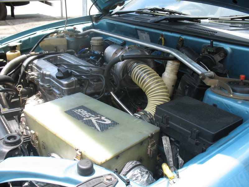
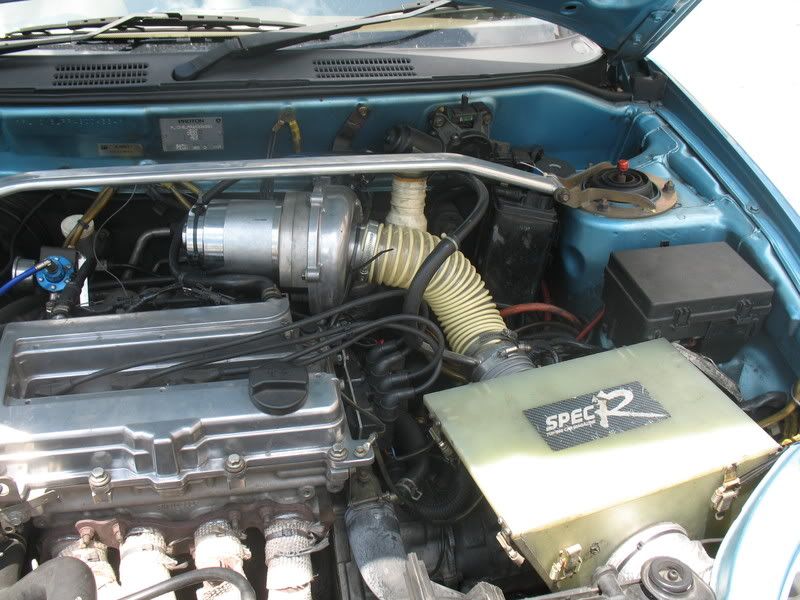
I almost forget to introduce my electrical supercharger or E-turbo that has installed for year . Since i going to bolt on turbo , i going to let go this stuff at Rm1800 (included installation ) . Prefer campro owner as buyer , if other car model also welcome but need to spend extra for piping . Welcome to drop message at shoutbox if you have inquiry . Above is the images of the machine .
Campro crankshaft broken issue
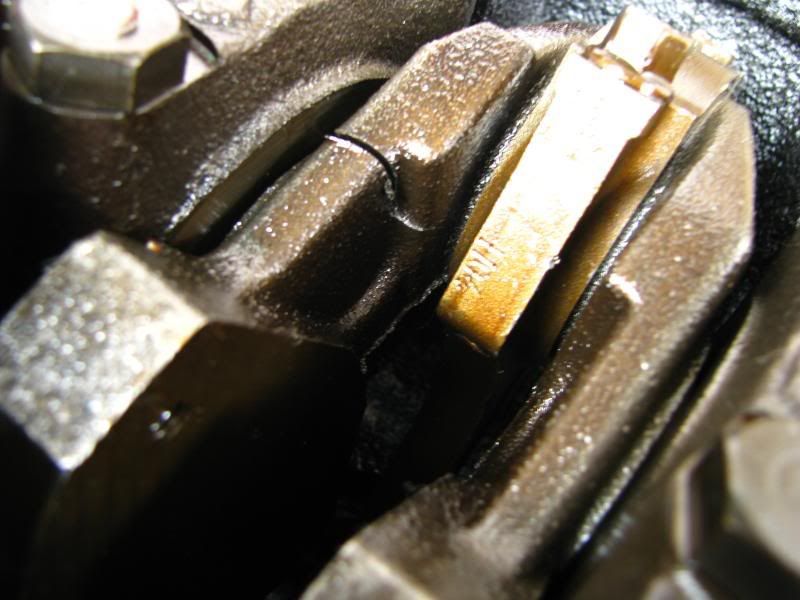
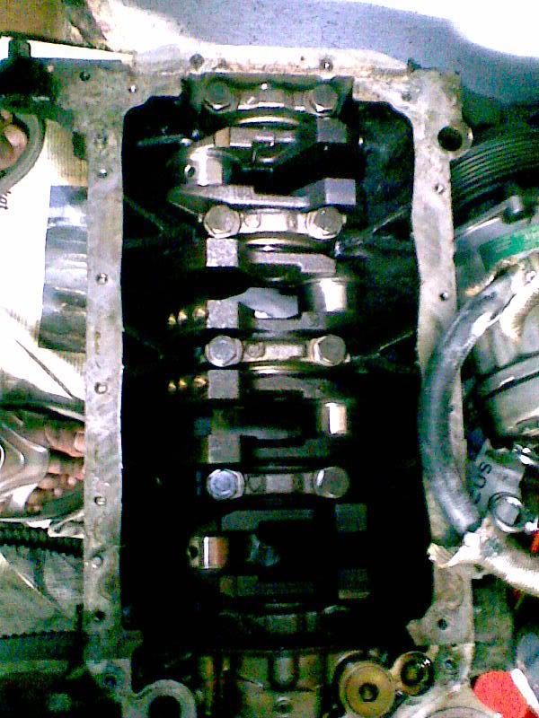
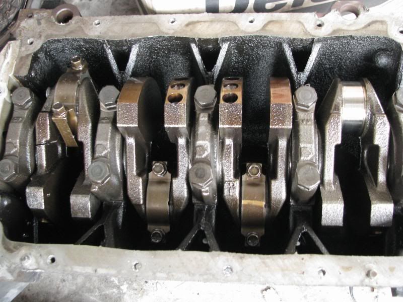
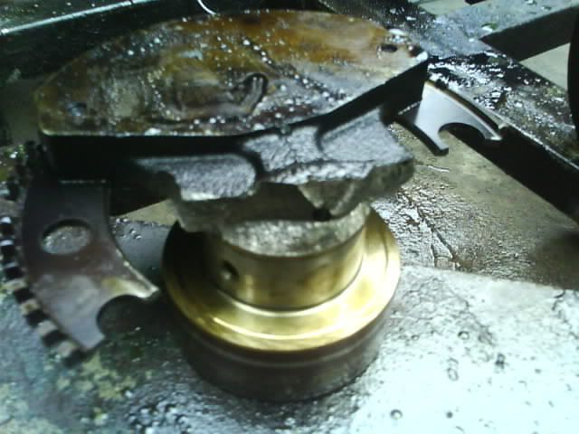
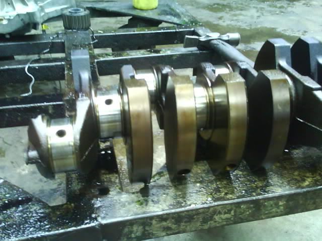
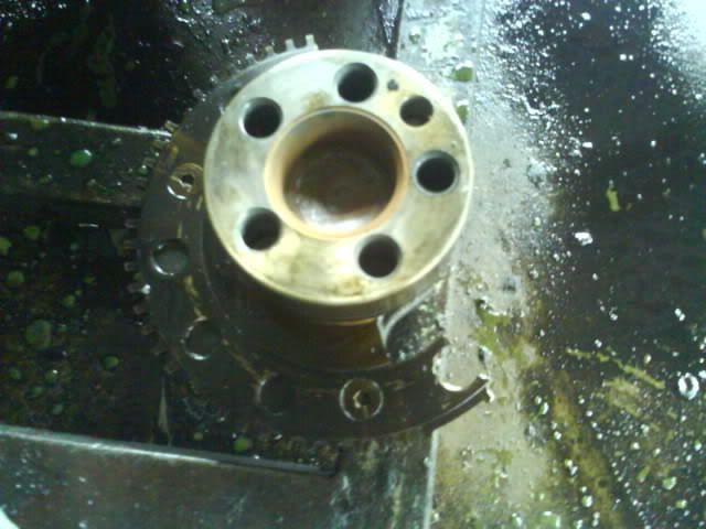
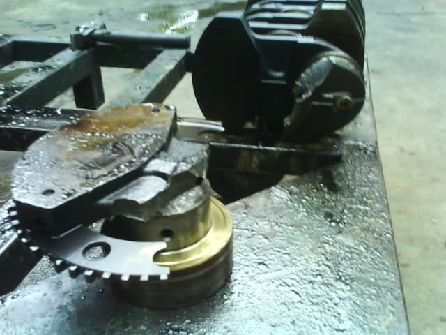
This is very hot issue now . This case has involved 6 cars total . Their campro reported can not start and then change crank sensor , but still fail to start . Once the oil sump removed , metal pieces everywhere inside the oil sump . Look at the crankshaft , found crack mark at the 4th crank weight balancer which near to flywheel . Some of them encounter even serious , whole crankshaft break into 2 pieces . Pls have a look at picture above .
Got a friend of mine who is working as mechanic in northern garage penang . Once he has seen the picture , he says he has handle numerous this type of case . Mostly he got turbo and NA machine that facing this problem . He says the impact of energy shock is the main root cause to twist the crankshaft until break apart . Normally will happen on those drag machine , because initial load is very huge impact for crankshaft take during launching time . Especially launching with maintain certain rpm , This will create very great impact and very high tendency to break the crankshaft . It might hurt the crankshaft and slowly crack day by day .
As i know those reported crankshaft broken campro machines are dragster . Hope that i am wrong about this :P :P . If normal driving , chance to break the crankshaft seem like very minimum . Anyway this case still need to blame proton doesn't use better material for the crankshaft . A 110 whp campro engine is far away to compare with turbo engine can easily to break their crankshaft . Unfortunately a 110 whp campro engine can break the crankshaft . :(
If you want to buy campro or campro cps for drag activity , you better stay away from do that . Use it as normal vehicle from A to B is fine .
Turbo a NA engine
Especially for youngster and some others whom performance minder , NA engine output power is under their expectation . Even they got the honda v-tec B16A type R , they still want to bolt on turbo . They can't find any excitement or wooh from that honda popular v-tec or screaming engine . Nowadays market full with engine which build to last and fuel save . Everybody struggling with petrol price hike . Everybody looking for fuel save , but then they also demand good performance from fuel save machine which is NA engine . That is never happen . In the end , they can't stand with poor performance of their so called " fuel save " machine . They looking for workshop that able to help them to boost some power of their " fuel save " machine . Come to workshop , mechanic will alway say you want immediate power and bolt on turbo is the choice . When the mechanic quote them price of turbo kit , they will faint with the figure . For bolt on turbo , easily touch RM7000 . Woh that figure is really make them to die heart and never think about immediate power again . In fact they never think , they have spent on those small upgrade nearly touch rm5000 - rm6000 in many months ago . They still can't get the expected performance . In the end , they give up to modify their " fuel save" machine and let it be .
If you want your fuel save machine or NA engine to boost more power , pls save more to bolt on a turbo . The price that you pay is far more worth it than you spend on those look cheap and not really improve performance . Although offered price of a turbo kit is 4 figure , it can satisfy you .
Next we will take about how to turbocharge a natural aspirated engine .


